Engineering Design Services:

Hardware

Software

FPGA

and more...

R&D

Consumer

Telecom

Test & Measurement

Bring your Ideas into Reality

or Tasked based Subject Matter Expertise

Turnkey Development

Mantaro...

Your Partner in Engineering!

Can ChatGPT be used in circuit design?

See our TechTalk series on this topic.

Impedance Calculators

These calculators are used by Mantaro engineers and provided freely for your use.
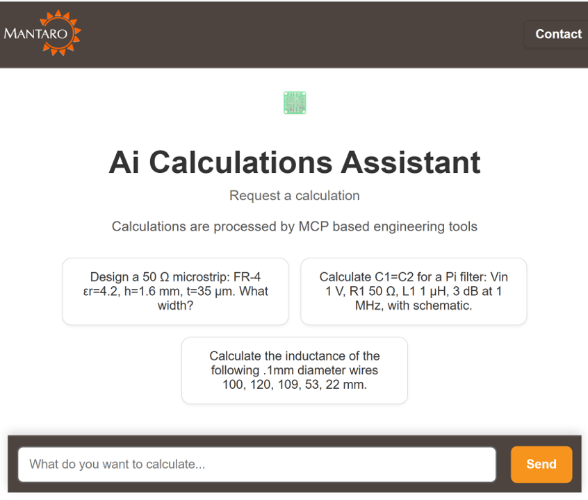
 If you have any suggestions for improvement please email This email address is being protected from spambots. You need JavaScript enabled to view it..

Calculator Group:
Wire Inductance

Dimensional units: mm mils

len (length) =
d (diameter) =
L (Inductance, nH) =

Strap Inductance

Dimensional units: mm mils

len (length) =
w (width) =
t (thickness) =
L (Inductance, nH) =

Air Core Solenoid

Dimensional units: mm mils

d (diameter) =
len (length) =
N (number of turns) =
L (Inductance, nH) =

Air Core Inductor

Dimensional units: mm mils

ID (inner diameter) =
AWG (magnet wire gauge) =
N (number of turns) =
L (Inductance - no leads, nH) =
D (wire diameter) =
d (inductor diameter) =
Len (Inductor Length) =
Wl (Wire Length - no leads) =
Rdc (DC Resistance, copper, no leads, mOhm) =

Air Core Flat Spiral Inductance

Dimensional units: mm mils

d1 (outer diameter) =
d2 (inner diameter) =
N (number of turns) =
L (Inductance, nH) =

Toroid Inductance

Dimensional units: cm inch

h (core width) =
D1 (outer diameter) =
D2 (inner diameter) =
ur (relative permeability) =
N (number of turns) =
L (Inductance, uH) =
Ae (effective core area) =
le (effective core length) =
Ve (effective core volume) =
B/I (Flux Density per Amp, gauss/A) =

Gapped Core Inductance

Dimensional units: cm inch

le (core length) =
Ae (core area = gap area) =
lg (gap length) =
ur (relative permeability) =
N (number of turns) =
L (Inductance, uH) =
Al (Inductance per turn ^2, nH) =
B/I (Flux Density per Amp, gauss/A) =

SI and SGS Magnetic Units
Mutual and Leakage Inductance
L1 (Inductance, uH) =
L2 (Inductance, uH) =
=
=
=
=
L1_leak (Inductance, uH)) =
L2_leak (Inductance, uH) =

Note: Calculations assume zero coil resistance


Parallel Wire Impedance Calculator

Dimensional units: mm mils

s (wire separation) =
d (wire diameter) =
er (relative dielectric constant) =

Zo (Impedance, Ohms) =

Coaxial Line Impedance Calculator

Dimensional units: mm mil

di (inner diameter) =
do (outer diameter) =
ur (relative magnetic permeability) =
er (relative dielectric constant) =

Zo (Impedance, Ohms) =

Skin Depth Calculator

Dimensional units: mm mils

rho (resistivity, nOhms*m) =
ur (relative magnetic permeability) =
TC (temp coefficient, ppm/C) =
T (operating temperture, Deg C) =
Fo (frequency, MHz) =
AWG (Wire Gauge) =

Default Material = Copper


Microstrip Impedance Calculator

Note: valid for (w/h) from 0.1 to 3.0
Dimensional units: mm mils

w (trace width) =
t (trace thickness) =
h (dielectric thickness) =
er (relative dielectric constant) =

Zo (Single Ended Impedance, Ohms) =

Note: 1oz = 1.4mils = 0.03556mm


Microstrip Impedance From Zo Calculator

Note: valid for (w/h) from 0.1 to 3.0
Dimensional units: mm mils

Zo (target impedance, Ohms) =
t (trace thickness) =
h (dielectric thickness) =
er (relative dielectric constant) =

w (trace width) =

Note: 1oz = 1.4mils = 0.03556mm


90 Deg Mitered Corner

Mitered bends are used to compensate for the impedance
discontinuity of the bend.

w (trace width) =
h (dielectric thickness) =

x (miter) =

Differential Microstrip Impedance Calculator

Note: valid for (w/h) from 0.1 to 3.0
Dimensional units: mm mils

w (trace width) =
d (trace separation) =
t (trace thickness) =
h (dielectric thickness) =
er (relative dielectric constant) =

Zd (Differential Impedance, Ohms) =
Zo (Single Ended Impedance, Ohms) =
Calculate w from Zd

Note: 1oz = 1.4mils = 0.03556mm


Differential Microstrip Impedance From Zo Calculator

Dimensional units: mm mils

Zo (single ended impedance, Ohms) =
d (trace separation) =
h (dielectric thickness) =


Zd (Impedance, Ohms) =
Calculate Zo from Zd
Calculate d from Zo and Zd

Embedded Microstrip Impedance Calculator

Note: valid for (h1/h) greater than 1.2
Dimensional units: mm mils

w (trace width) =
t (trace thickness) =
h (trace dielectric thickness) =
h1 (overall dielectric thickness) =
er (relative dielectric constant) =


Zo (Impedance, Ohms) =

Note: 1oz = 1.4mils = 0.03556mm


Stripline Impedance Calculator

Note: valid for (w/h) from 0.1 to 2.0 and (t/h) less than 0.25
Dimensional units: mm mils

w (trace width) =
t (trace thickness) =
h (dielectric thickness) =
er (relative dielectric constant) =

Zo (Impedance, Ohms) =

Note: 1oz = 1.4mils = 0.03556mm


Differential Stripline Impedance Calculator

Note: valid for (w/h) from 0.1 to 2.0 and (t/h) less than 0.25
Dimensional units: mm mils

w (trace width) =
d (trace separation) =
t (trace thickness) =
h (dielectric thickness) =
er (relative dielectric constant) =

Zd (Impedance, Ohms) =

Note: 1oz = 1.4mils = 0.03556mm


Differential Stripline From Zo Impedance Calculator

Dimensional units: mm mils

Zo (single ended impedance, Ohms) =
d (trace separation) =
h (dielectric thickness) =


Zd (Impedance, Ohms) =

Asymmetric Stripline Impedance Calculator

Note: valid for (w/h) from 0.1 to 2.0 and (t/h) less than 0.25
Dimensional units: mm mils

w (trace width) =
t (trace thickness) =
h (smaller dielectric thickness) =
h1 (larger dielectric thickness) =
er (relative dielectric constant) =


Zo (Impedance, Ohms) =

Note: 1oz = 1.4mils = 0.03556mm


Broadside Coupled Stripline Impedance Calculator

Note: valid for (w/h) from 0.1 to 2.0 and (t/h) less than 0.25
Dimensional units: mm mils

w (trace width) =
t (trace thickness) =
h (outer dielectric thickness) =
h1 (center dielectric thickness) =
er (relative dielectric constant) =


Zo (Impedance, Ohms) =

Note: 1oz = 1.4mils = 0.03556mm


Plane Impedance Calculator

Note: valid for w>>h
Dimensional units: mm mil

w (width) =
h (height) =
ur (relative magnetic permeability) =
er (relative dielectric constant) =

L (inductance, nH) =
C (capacitance, pF) =

Rectangular Pad Capacitance Calculator

Note: valid for w>h and len>h, includes fringing capacitance
Dimensional units: mm mil

w (pad width) =
len (pad length) =
h (height) =
t (trace thickness) =
er (relative dielectric constant) =

C (capacitance, pF) =

Pad Capacitance and Thermal Resistance Calculator

Note: valid for w>>h and len>>h (excludes fringing capacitance)
Note: FR4 Thermal conductivity = 0.24 to 0.34 W/(m.K)
Dimensional units: mm mil

w (width) =
l (length) =
h (height) =
er (relative dielectric constant) =
ro (thermal conductivity, W/(m.K)) =
A (Cumulative Area, mm^2) =
C (capacitance, pF) =
k (Thermal Resistance, Deg C/W) =

Capacitively Loaded Transmission Line Calculator

Dimensional units: mm inch

Zo (unloaded trace impedance, Ohms) =
Tpd (unloaded propagation delay, ps/unit len) =
Cl (distributed capacitve load, pf) =
len (transmission line Length) =

Zl (loaded Impedance, Ohms) =

1%, 5%, 10% Component Value Calculator


Target Value =
Nearest 1% Value, %Error =
Nearest 5% Value, %Error =
Nearest 10% Value, %Error =
R1= R2=
Parallel Value, %Error =
R3= R4=
Series Value, %Error =

1% Resistor Divider Calculator

Target Vin (V) = adjusts A,dB,R2
Target Vout (V) = adjusts A,dB,R2
Target R1 = adjusts R2
Target R2 = adjusts R1
Target A (lin gain) = adjusts Vout,dB,R2
Target dB (dB gain) = adjusts Vout,A,R2
1% R1, %Error =
1% R2, %Error =
1% Vout (V), %Error =
1% A(Lin Gain), %Error =
1% A(dB), dB_Error =
1% Rin, Rout =
Vout %Tol (From 1% Component Tolerance) =
Vout %Tol (From 0.1% Component Tolerance) =

Note: %Error indicates the nominal difference to the target valuedue to value selection. %Tolerance indicates the additional +/- part to psrt variation due to manufacturing accuracy.


Pi and Tee Attenuator Pad Calculator
Port 1 Characteristic Impedance, Z1 (Ohms) =
Port 2 Characteristic Impedance, Z2 (Ohms) =
A (Attenuation, dB) =

Pi Attenuator Pad:

      R1 ( Ohms) =
      R2 ( Ohms) =
      R3 ( Ohms) =

Tee Attenuator Pad:

      R1 ( Ohms) =
      R2 ( Ohms) =
      R3 ( Ohms) =

Y and Delta Network Transformation Calculator
Y Impedance, R1 (Ohms) =
Y Impedance, R2 (Ohms) =
Y Impedance, R3 (Ohms) =

Transform Y to Delta:

Delta Impedance, Ra (Ohms) =
Delta Impedance, Rb (Ohms) =
Delta Impedance, Rc (Ohms) =

Transform Delta to Y:

Add Series/ Parallel Resistor:


1:N Resistive Splitter Calculator
Port Characteristic Impedance, Zo (Ohms) =
N (Number of split ports, 1:N) =
A (Attenuation, dB) =

Series Resistance - R1 ( Ohms) =
Shunt Resistance - R2 ( Ohms) =

Smith Chart Tutorial

The Smith Chart graphically maps S11=reflection coefficient=(ZL-Z0)/(ZL+Z0) to Load Impedance (ZL), normalized to Z0 (source impedance = center of chart). The Smith Chart achieves this by superimposing a grid on S11 that maps load impedance. Polar or rectangular grids only allow direct reading of S11.
Notice that the location of the marker is independent of grid type, and only the Smith Chart grid enables reading the load impedance (ZL) by inspection. SWR circles are also provided for the sake of illustration. An Admittance Chart(YL=1/ZL) is provided for illustration as well.

  • Click the Z_Load buttons to see impedance examples
  • A Match is at dead center (reference impedance Z0 )
  • A Short is at the far left
  • An Open is at the far right
  • Pure real impedances are along the horizontal axis
  • Pure imaginary impedances lie along the unit circle
  • Constant real impedances lie along circles
  • Constant imaginary impedances lie along semi-circles
  • To calculate absolute impedance multiply the Smith Chart result by Z0

Click buttons below to view S11 with on different grids:

  • All choices generate the same grid-less position (X,Y)=(S11re,S11im)
  • The Smith Chart grid reads ZL=(ZLre,ZLim)
  • The Polar grid reads S11=(S11mag, S11phase)
  • The Rectangular grid reads S11=(S11re,S11im)
  • The SWR grid reads SWR=(1+|S11|)/(|1-S11|)
  • The Admittance Chart grid reads YL=1/ZLin=(YLre,YLim)
  • Adding series inductance moves clockwise along constant resistance circles
  • Adding series capacitance moves counter-clockwise along constant resistance circles
  • Adding shunt inductance moves clockwise along constant admittance circles
  • Adding shunt capacitance moves counter-clockwise along constant admittance circles
  • Use the Series and Shunt Impedance Calculator:to try your own impedances

Change Grid:

S11, (ZL normalized to source impedance Z0)

Z_Load


Z_Load


Matching Network Calculator
Port Z1 Real, Imaginary Impedance (Ohms) = , j
Port Z2 Real, Imaginary Impedance (Ohms) = , j
Operating Frequency, Fo (MHz) =

Lower, Higher Impedance Port:

ZLOW= ZHIGH=

Option 1 Matching Impedance (Ohms):

ja= jb=

Option 2 Matching Impedance (Ohms):

ja= jb=

Series and Shunt Impedance Calculator
S11, normalized to source impedance ZS Change Grid:


Reset to:


Operating Frequency (MHz) =

, j


,
Series Impedance (ZL=a+jb) Ohm = , j
Parallel Impedance (ZL=c//jd) Ohm = , j
ZL (Ohm, deg) = , ∘
YL (1/r,j/x sec) = , j
S11 (Re+jIm) = , j
S11 (dB, deg) = , ∘
VSWR =
, j

Return Loss S11, and VSWR Calculator
Port Z1 Real, Imaginary Impedance (Ohms) = , j
Port Z2 Real, Imaginary Impedance (Ohms) = , j
Reflection Coefficient (Lin Mag,Deg) = ,
Return Loss = S11 (dB, Deg)= ,
Mismatch/Through Loss (dB)=
VSWR =

Disclaimer: While we endeavor to keep the information on this web page up to date and correct, Mantaro makes no representations or warranties of any kind, express or implied, about the completeness, accuracy, reliability, suitability or availability with respect to the website or the information, products, services, or related graphics contained on the website for any purpose. Any reliance you place on such information is therefore strictly at your own risk. In no event will we be liable for any loss or damage including without limitation, indirect or consequential loss or damage, or any loss or damage whatsoever arising from loss of data or profits arising out of, or in connection with, the use of this website.


Robot Design & Development Services

OceBot GIF bushes small AdobeCreativeCloudExpress 1


Click image for more Robot Videos

(they open in new tab)


Go to top